
Worked example · public data

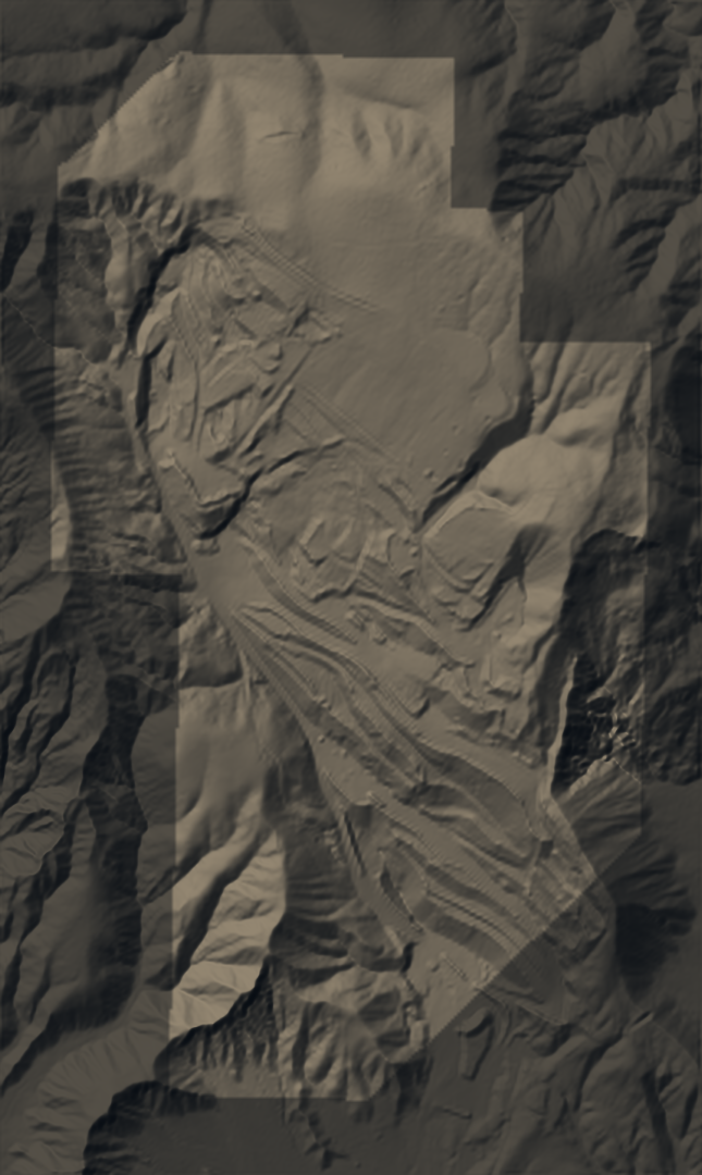
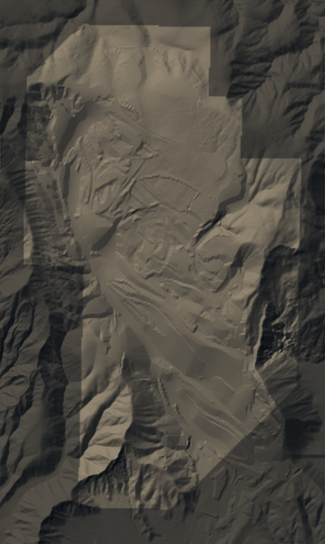
Cuyama quarry reclamation concept

What the proposed grading changes, and what it leaves alone.

PUBLIC USGS 3DEP 2018 · 2016 PERMIT RECORD · NOT A GPSCS CAPTURE CONCEPT MODEL · NOT A GRADING DESIGN
Landslide envelope Scraping boundary

Vertical exaggeration ×1.5

Drag the terrain to orbit · drag the divider to compare

On the surface · engine run

Where the water goes, before and after.

The GPSCS drainage engine routed runoff across the 2018 terrain and across each proposed surface. Switch surfaces to compare where flow concentrates and where water would sit.

SURFACE

Flow paths and ponding

Flow paths and ponding basins computed by the GPSCS drainage engine from this surface.

  • Flow path; wider and brighter where more ground drains to it
  • Moving marks show direction only
  • Ponding basin; point at it for its depth
    Engine results on each surface
    00:00 / 00:00

    Terrain-based screening on historical 2018 public terrain and on proposed concept surfaces. Not a hydrologic or hydraulic design: rainfall, infiltration, channels, culverts and pipes are not modeled, and moving marks show direction, not speed.

    Data and method

    Earthwork · exact TIN quantities

    Where the ground comes down, and where it goes up.

    Proposed surface minus the 2018 terrain, cell by cell. Cut and fill integrate that difference exactly over the triangulated 5 m grid, splitting each triangle where the change crosses zero.

    Elevation change, proposed minus 2018

    Cut (lower)Fill (higher)

    • Landslide envelope (photo interpretation)
    • Scraping boundary, 2016 permit disturbance
    • Additional work outside the historical outline
    • Unresolved area in the earlier concept
    Earthwork for each model against the 2018 terrain. Volumes are exact TIN integrals, rounded to the nearest 100 cubic yards.

    Two models, one audit

    The same checks on every surface.

    Each surface is measured by the same code, so the numbers compare line by line. Where the audit disagrees with a model's own figures, the difference is scope, and the table says which scope it used.

    Audit of each model against the 2018 terrain

      The proposal · what the concept commits to

      Local recontouring, built and checked in stages.

      What the concept covers, how it would be built and verified, and what is still open before any construction. Numbers in brackets point to the references at the end.

      Scope

      The 2016 permit's blue-boundary disturbance area, about 135 acres on provisional mapping, is planned for scraping and treated as disturbed, except a landslide no-work envelope [4]. Grading is local recontouring on the historical 2018 terrain [5], with a 2 horizontal : 1 vertical maximum on the proposed interior surface.

      The landslide envelope is a conservative photo interpretation, not a mapped geotechnical limit. The west access road alignment is retained; its elevations, width and profile need a separate road design. Additional work areas outside the historical outline carry a strong preservation penalty.

      Landform

      Local reshaping that keeps the ridges and the drainage cues already on the ground. The 2:1 maximum is enforced on every proposed interior triangle [1][2].

      Drainage

      Use the engine's flow paths to guide review. Confirm upstream inflows, natural outlets and the convex-to-concave slope transitions, then size channels and outlet protection from site hydrology [2].

      Roads

      Retain the west route as requested and resolve its profile, its drainage crossings and its connection to the regraded slopes. Rip, recontour and revegetate the other retired roads within verified work limits [4].

      Growth media

      Identify salvaged soil and gypsum-rich spoil separately. Test rooting conditions, salinity, nutrients and amendment compatibility before placement, and avoid a uniform imported soil blanket without a basis for it [3].

      Revegetation

      Locally native dryland vegetation in test patches and planting islands, across contrasting aspects and substrates. Hydroseeding only where trials support it [1][3].

      Verification

      Build and measure a pilot landform. Inspect it after runoff-producing storms, repeat fixed-point vegetation and erosion observations, and set acceptance criteria from local reference areas and the applicable plan [2].

      Sequence

      1. Confirm the current terrain and the scope.
      2. Design and test a representative pilot.
      3. Measure the completed pilot.
      4. Adjust the grading and planting treatments.
      5. Expand in manageable areas.
      6. Monitor and repair.

      Open items

      • Plan-to-LiDAR registration of the 2016 sheets is unresolved: section A appears displaced about 50 m, and section E carries about an 80 ft vertical offset.
      • A current topographic survey by a licensed land surveyor is required before construction.
      • Landslide boundary and geotechnical review.
      • Material suitability, shrink and swell, compaction, and topsoil.
      • Haul and access.
      • Hydraulic channel and outlet design.
      • Road engineering.
      • The permit's stricter finished-slope requirement, 3:1 in areas 1 to 4 per the 2016 record, must be honored where it applies [4].

      Concept model on historical public terrain. Not construction quantities, staking, machine control, slope-stability design or drainage design.